

Smart Material Solutions’ novel nanopatterning process - Nanocoining - has a unique origin story within the nanotech world. Unlike most nanopatterned mold-making techniques that require a lithographic techniques like those used to make computer chips, Nanocoining is based on a mechanical indenting process that is derived from diamond turning.
Diamond turning is, simply put, cutting a part on a very precise computer numerical control (CNC) lathe using a sharpened diamond tool. The process involves mounting the part on a spindle that rotates the part (a copper cylinder in the video on the right) while a diamond tool drags across the part’s surface to cut it. The resulting spiral cut around the surface creates a single chip that can be miles long. The diamond tool is so sharp and the CNC axes so precise that diamond turning can simultaneously control both the form (or shape) and surface finish, even for optics that require an extremely smooth mirror finish. Surface roughness as small as 1 nm root mean square (RMS) can be achieved with an air-bearing spindle and air- or oil-bearing linear axes.
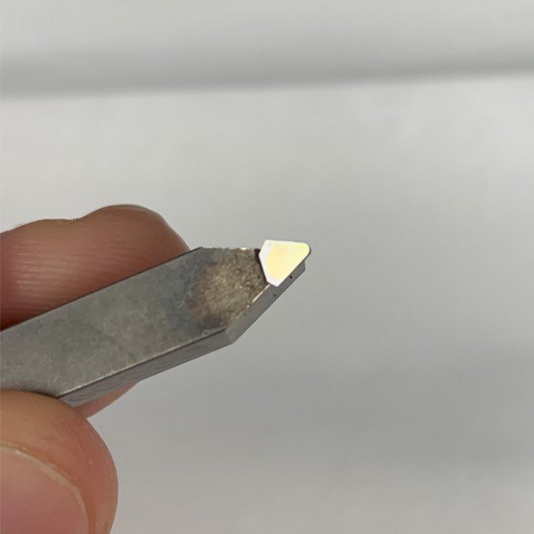
A high-quality optic will have form errors less than one sixteenth of the smallest wavelength of interest, meaning that for visible light (down to 390 nm), form errors have to be less than 25 nm! To produce a mirror-like surface with minimal diffractive effects, the surface finish has to be even better, often less than 3 nm RMS. The ability to produce high-quality surface finish in the cutting step eliminates the need for a polishing process. However, this requires not only an atomically sharp tool and stiff, precise axes, but also careful control of the chip via, for example, a vacuum (video on right) to ensure it does not damage the part. During a good cut, this chip should be a continuous string that is a few micrometers thick and wide, but tens of kilometers long.
A Deterministic Process

Geometry of the grooves formed during a diamond-turning process.
In diamond turning, surface finish is derived primarily from the size of the grooves left by the diamond tool as it cuts a chip from the part. The sketch on the right shows how theoretical kinematic roughness is affected by the tool radius and crossfeed, or how far across the part the tool moves per revolution. Equation (1) gives an approximation for the peak to valley (PV) surface roughness as a function of crossfeed and tool radius. For this geometry, RMS roughness is a third of PV roughness, so a small crossfeed is needed to ensure a high-quality surface finish.
|
PV roughness = |
crossfeed2
8*tool radius
|
(1) |
Other metrics that affect cut quality include cut speed, depth of cut, and cut distance, which often must be balanced with crossfeed. However, cutting a part with a fine crossfeed increases cut distance, Equation (2), leading to more tool wear and eventually a degradation of surface finish.
|
cut distance = |
part diameter*π*traverse
crossfeed
|
(2) |
|
cut speed = |
part diameter*π
spindle RPM
|
(3) |
Fine crossfeeds also add to processing time (cost) and the likelihood of temperature changes affecting the part’s shape. High cut speeds reduce processing time, but increase sliding velocity which increases temperature, and at some point, tool wear. Regardless, so long as these process parameters can be controlled, the same set of inputs should create a repeatable part and metrology can be used to determine errors that can be compensated out. This is known as a deterministic process.
Materials and Form Factors
Diamond turning is best suited for cutting non-ferrous materials like aluminum 6061, brass, copper, or electroless or electrolytic coatings, like copper or nickel doped with high concentrations of phosphorous. These electroformed materials are attractive because of their superior hardness, extremely fine grain size, and, ideally, low incidence of impurity. Using these materials along with a proper lubricant, a diamond tool can remain sharp for miles of cut distance - enough to cut a surface with an area greater than a square meter. Ferrous materials like steel are typically avoided because they rapidly wear the diamond tool.
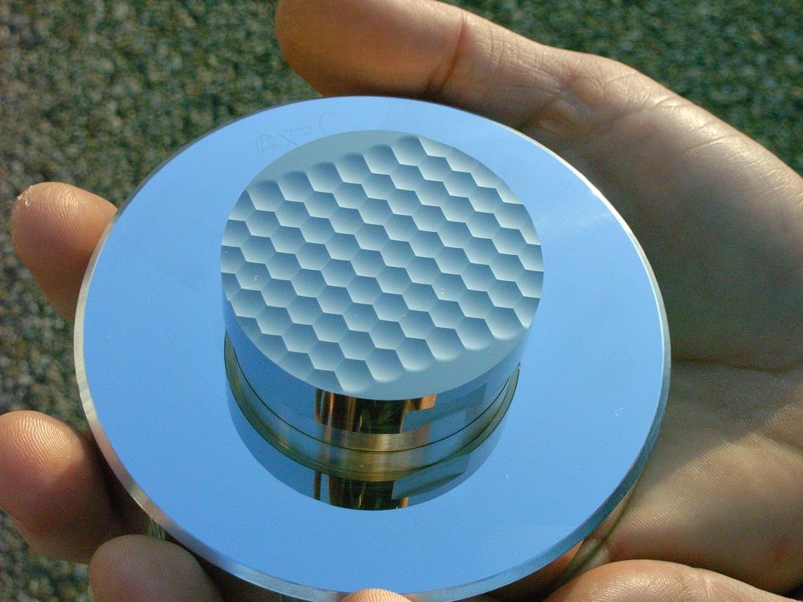
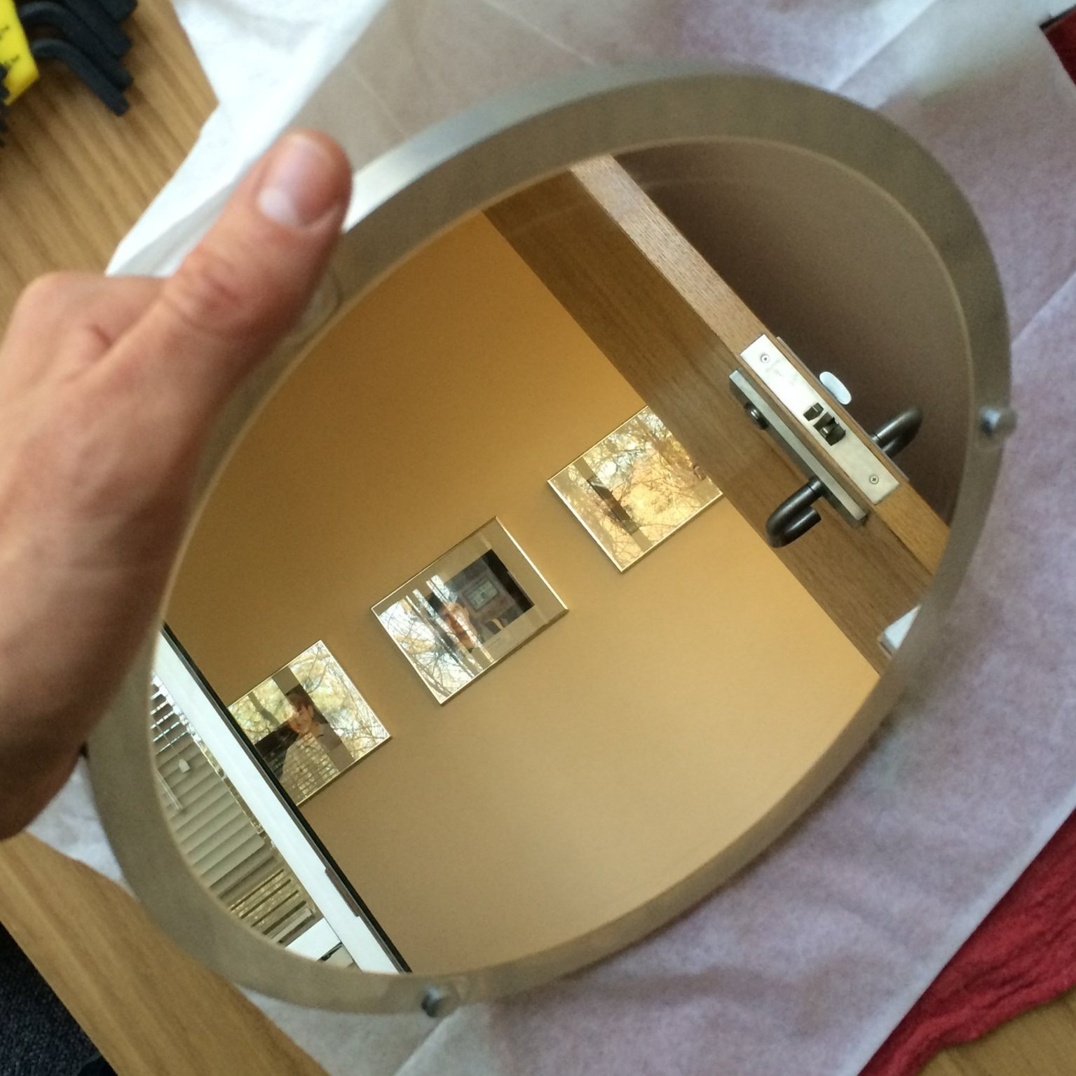
Since diamond turning is done on a lathe, radially symmetric components are easily accessible. This includes cylinders or spherical or parabolic optics. However, the addition of supplemental machine axes such as a Fast Tool Servo that can plunge in and out in sync with the rotating spindle allows for the creation of non-radially symmetric or “free-form” optics. Other methods such as mounting a part off center on the spindle, enables creation of non-radially symmetric conic sections. Photos of both radially and non-radially symmetric diamond-turned parts are shown below.
Nanocoining relies heavily on extremely precise controls processes that are maintained at high speed. However, by borrowing from the deterministic tool kit developed for diamond turning, Smart Material Solutions is able to limit alignment errors and maintain low defect rates, even while tiling billions of indents on a seamless drum mold.
Acknowledgements:
Byron Knapp, Professional Instruments.
Chris Morgan, Moore Nanotech.